Dynamic EFI
Bringing TBI and Multi Port Fuel Injection to a New Level.
Embedded Lockers Board Installation Guide
This guide is to help with the installation of the EBL Flash or Classic board into the ECM. Please note that no work was actually done where these pictures were taken. All of the actual work was done either outside (cleaning and little board removal), or on a work bench (cover mods, soldering in of EBL).
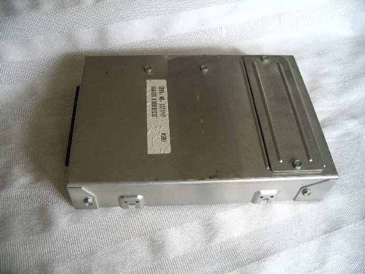
The typical C3 TBI ECM. Remove the 8 hex head screws. There are 6 visible here and 2 more on the far side.
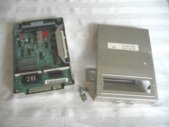
ECM with cover removed. No need to remove the board from the lower case.
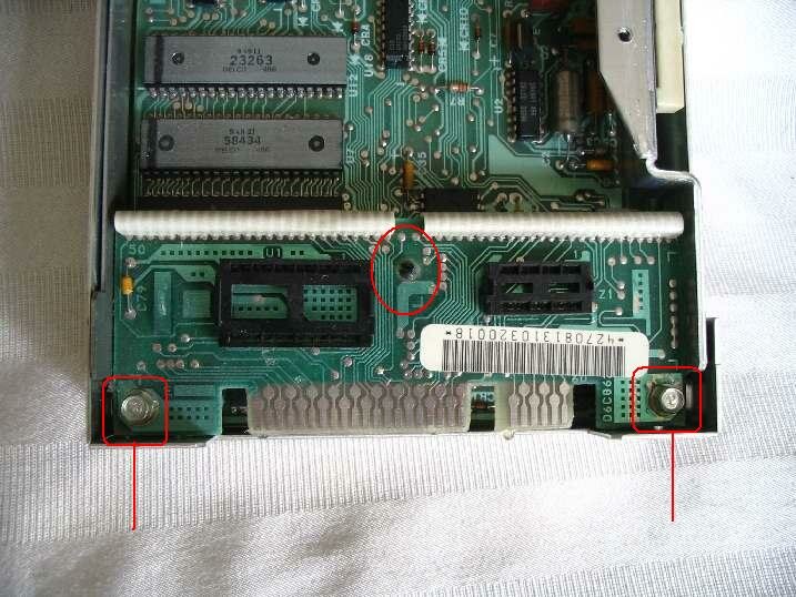
Remove the 2 screws in the lower corners. The small post circled in the center needs to be broke free of the board. It is still required so don't destroy it. Soaking it with a little brake cleaner (will be shown a few pictures further down) will help soften the conformal coating.
Note the PROM and CALPAK have been removed. The CALPAK is still required for the EBL board. The PROM may be used as a desk ornament.
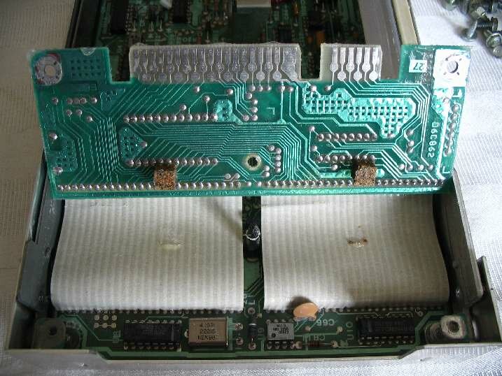
Here you can see some coating still on the post. This is what makes it difficult to free from the little board. Remove the small cork cubes and carefully free the ribbon cables from the back side of the little board. The conformal coating sometimes glues them in place.
Note: The ribbons cables (white in color) are required for the EBL install. Take care to not damage them. The little board is no longer required, so we don't need to be careful with it.
The ribbons cables need to be de-soldered from the little board. Remember to be careful with the ribbon cables at all times.
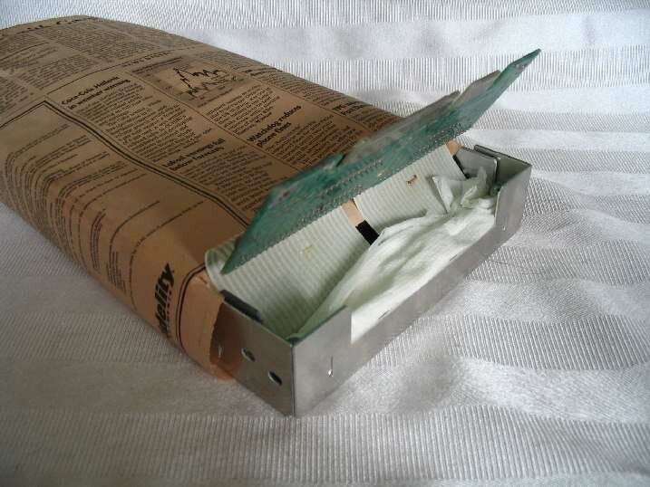
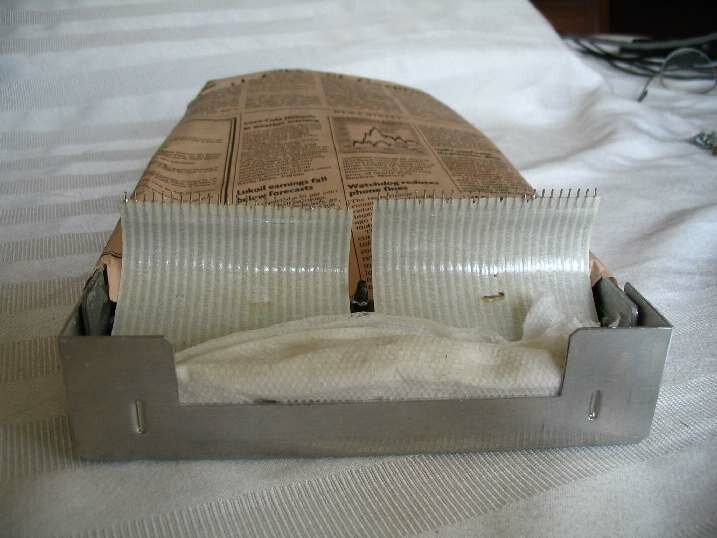
Wrap the ECM with some paper (newspaper used here and taped on the bottom to hold it in place), and stuff a folded paper towel down in front.
This is to protect the ECM from brake cleaner and handling damage.
The conformal coating needs to be removed from where the ribbon cable meets the little board. This only needs to be done to the top side. Cleaning the bottom side can also be done.
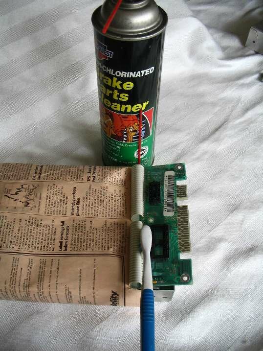
Used is the non-chlorinated brake cleaner (green can) and a toothbrush. Wet the brush with the cleaner and scrub along where the ribbon cable meets the board. Be careful to not have the cleaner drain down into the ECM.
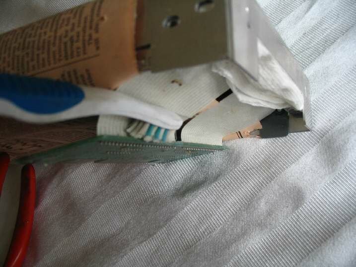
This shows the other side of the ribbon cable being cleaned. The ECM is set up so the cleaner won't run down the ribbon cables. It is sorta upside down on an angle.?
Now it is time to de-solder the ribbon cables from the little board. The method I use and will show here is to use a small torch. In this case it is a plumbers propane torch. Others have reported good luck using a small butane torch (like a jewelers torch).
Another method would be to use a soldering iron and either wick or a pull-it tool. An iron with a reasonable size tip and of 45 watts will do the trick.
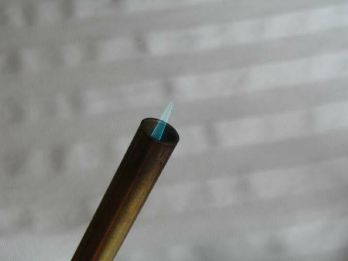
Here is the flame size to use. Note that it is a low flame. This will be played across the solder joints.
This picture gives the general idea of desoldering the little board. Play the torch flame onto the solder joints while moving it along those same joints. Keep the flame moving back and forth. Sit in one place too long and?the board will catch fire. If it starts to char keep moving.
The ends tend to not get enough heat. Look at the solder as you heat it. It is obvious when it melts. Don't pull too hard on the little board, it will fall off once all of the solder joints have melted.
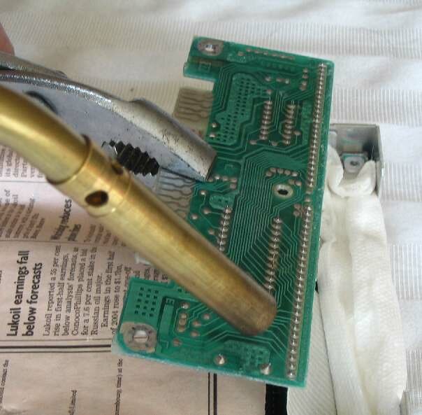
I play the flame to the board from the direction shown. If you come in from the other direction it is easy to torch the ribbons cables. Don't want to do this, need the?cables to install the EBL board.
Note: some ECMs have the CALPAK soldered in. Once the little board is removed from the ribbons cables the CALPAK may be desoldered. Hold the little board upright?and heat up the CALPAK solder joints from the bottom. Once the solder is melted gently pry the CALPAK out. It may take a little time as the conformal coating tends to glue it in place. So don't fry the CALPAK, just keep it warm as it is lossened from the board.
If you wish the CALPAK can be soaked in cleaner to remove more of the conformal coating. Then heat and remove it from the little board.
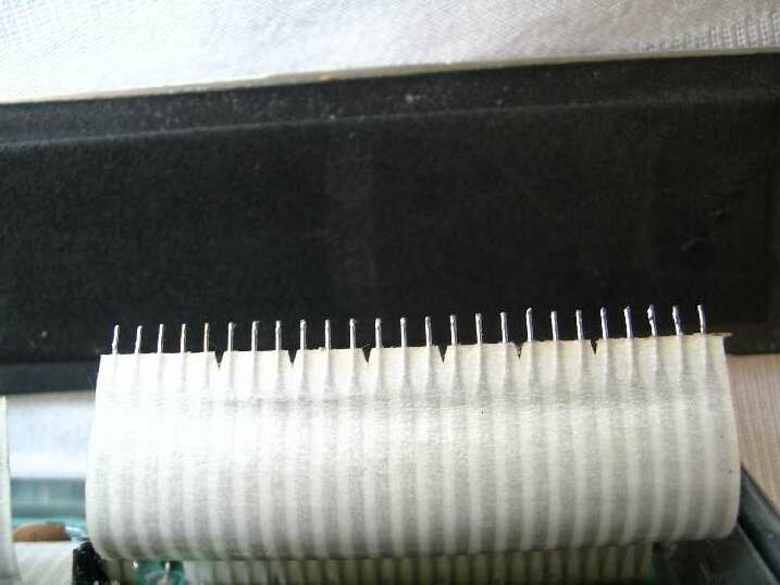
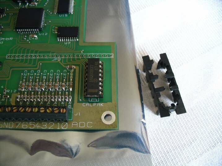
Here is the ECM with the little board removed. Note how some ribbon cable pins have a little extra solder on them. And, the end pins are a little bent (note far right pin). The bent pins is normal, probably an assembly aid for GM.
Use some solder wick and remove any excess solder. A pair of needle nose pliers can be used to straighten up the pins a little. No need to have them perfectly straight, just a little better will help.
If the CALPAK was soldered in it too can be cleaned up with some solder wick.
Here the pins have been cleaned up and are ready for the EBL board to be installed. A trick is to draw the soldering iron from the base of the ribbon cable toward the tip of the wires. This leaves any solder as a spear point on the tips. In that case it does not interfere with inserting the wire ends into the EBL board.
Caution: make sure that the board is oriented in the proper direction. See the next couple of pictures along with the last one! If you solder the board in backwards, that is 50 solder joints to undo.
The connectors face the outside end of the ECM, same as the original little board.
This is the trickiest part of the whole install. Sometimes the ribbon cable just doesn't want to cooperate. If the pins won't go into the holes it may be from too much solder on one of them. Whatever you do, don't try to force them. If the pins are cleaned up of solder they will go right in. I usually start them at one end and the rest just fall into place.
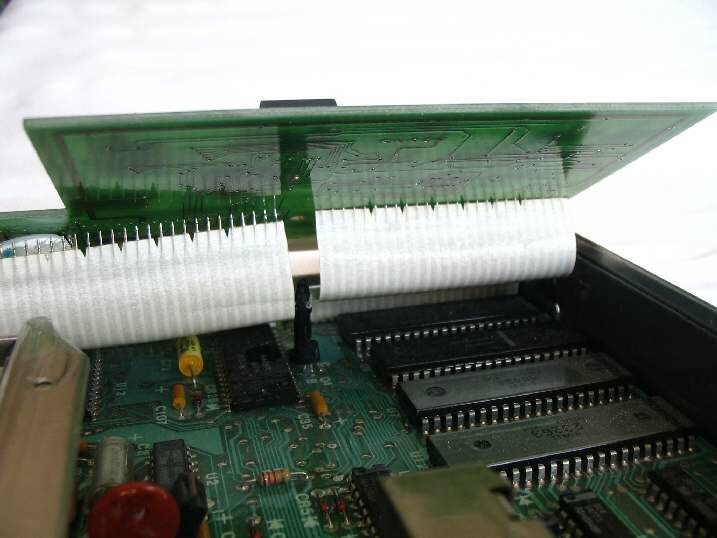
Here the EBL board has had one of the ribbon cables inserted into the holes. See the next picture for a better idea of the EBL board orientation.
Once one cable is inserted, at the least solder the end pins. This will prevent it from falling out while futzing with the other cable.
Here the one cable is being soldered in. The other cable has not yet been inserted. (Not representative of soldering technique. Picture was taken with one hand while I held the cold iron with the other. The body of the soldering iron should be further up off of the chips!).
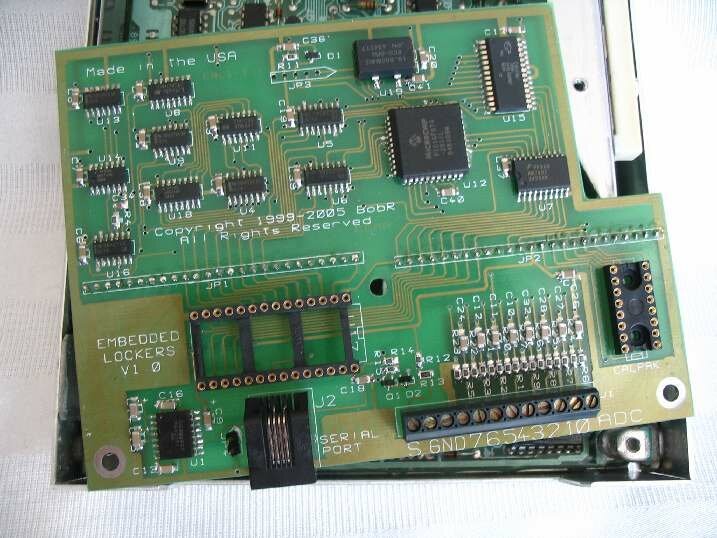
Both cables inserted and soldered. The board can be pivoted under the heat sick (on the right) and snapped down over the center post.
Using a small piece of paper towel wet with brake cleaner remove the flux from the soldering. Be careful to not slop it all over as it will remove the conformal coating.
Put the two end screws back in place to hold the EBL board in. Just like the original little board.
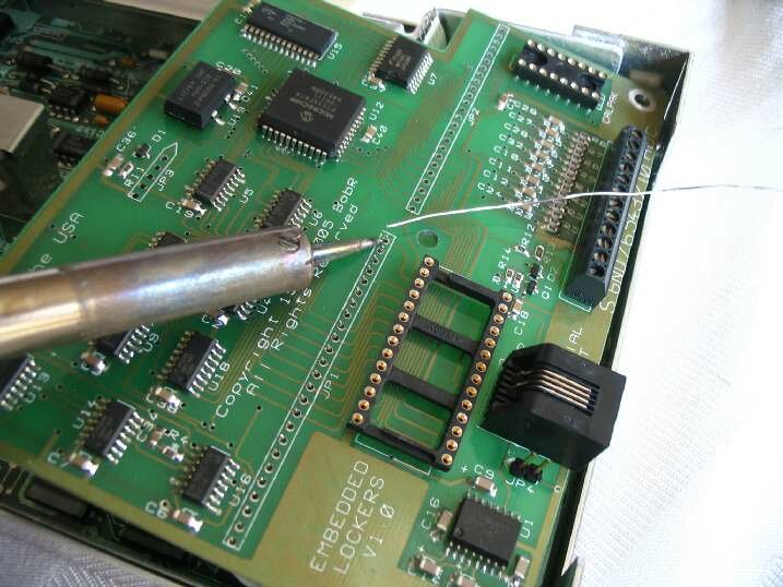
Notice the EBL board is down in place and the center post can be seen (under the pliers).
No Picture yet: The ribbon cable solder joints can be protected with RT. Use some sensor safe RTV and put a thin coat over the solder joints.
Case Modification
There are a couple of mods required on the ECM case. The end flap needs to be removed along with an interior tab.
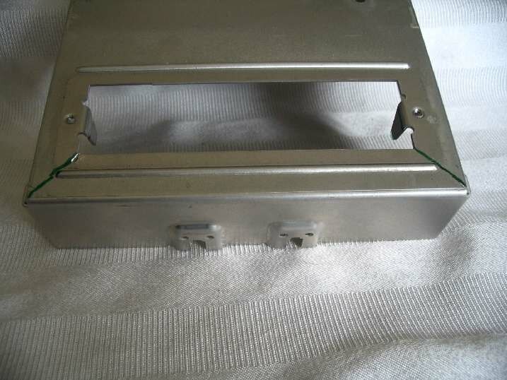
The green maker lines show were the cuts are required to remove the end flap. One of several tools can be used. A hacksaw with a fine tooth blade, band saw, or a dremel with a cutoff wheel will all work.
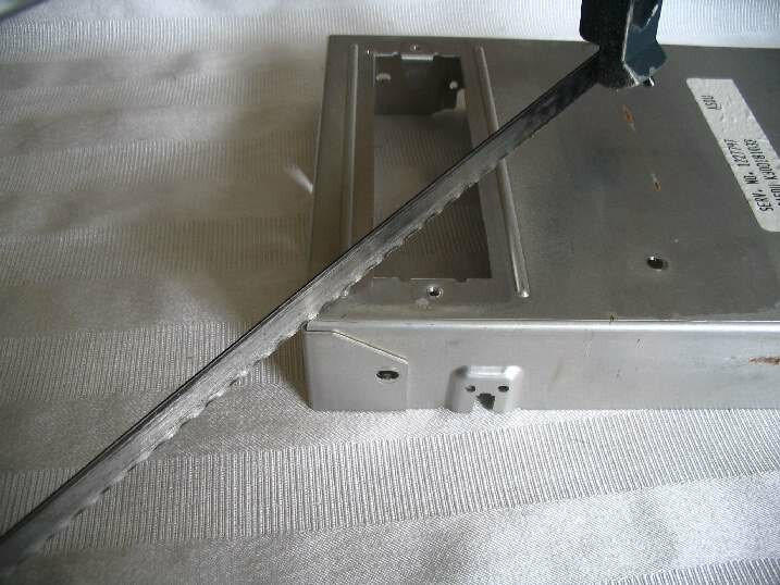
Here a hacksaw is being used. Tipping the blade back will help prevent cutting into the cover on the far side of the opening.

Clean up the cut edges. Either a file, sandpaper,?or a?sanding drum in a dremel will work.
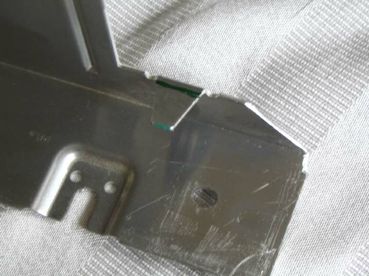
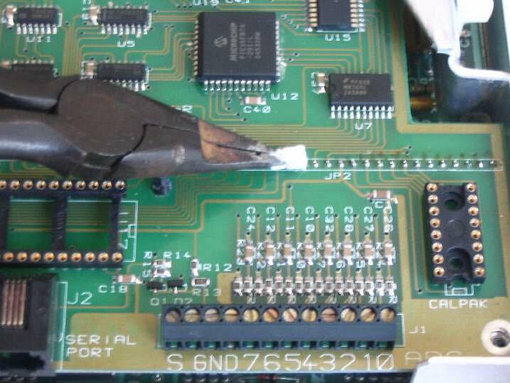
This tab needs to be removed. Note the green line towards the top.
Note: for the EBL Flash, both tabs need to be removed. Cut the one shown along with the one opposite of it.
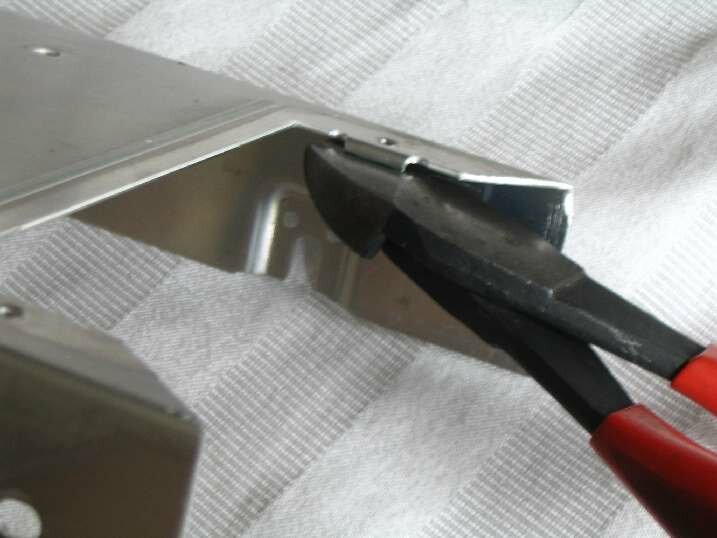
A pair of wire cutters make short work of the removal process, snip.
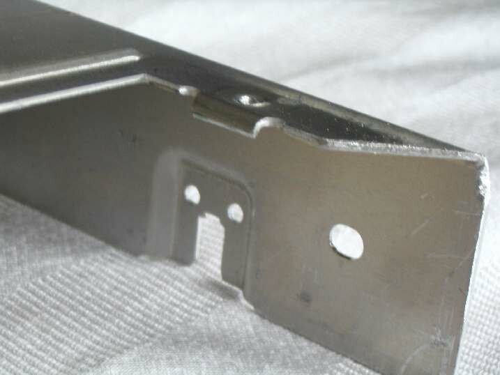
Gone. This tab would otherwise hit the CALPAK.
Note: for the EBL Flash, both tabs need to be removed. Cut the one shown along with the one opposite of it.
This picture shows the orientaion of the CALPAK. Note the white strip across the end of the CALPAK. That signifies the pin 1 end. To remove the CALPAK from the carrier use a pair of cutters and snip the carrier in half.
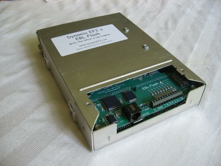
Put the CALPAK into the socket (far right of EBL board), put the cover aong with the end cover on with 6 screws, and you are ready to go.
? ? ?
Copyright 2006-2011 Dynamic EFI, All Rights Reserved.
No part of this document may reproduced in any form or posted on a?web site without expressed documented permission from Dynamic EFI